Microcontroller Unit Lab 8
RC Servo Control Signals
Summary
Use a microcontoller to provide a pulse width control signal for an RC servo.
Pt. 1 Create a simple repeated movement sequence using CPU-timed pulses
Pt. 2 Add two buttons. Each should move the servo by a fixed angle increment. One for clockwise and one for counterclockwise rotations.
Pt. 3 Replace the CPU timing with Pulse Width Modulation control where the PWM freqency controls the motor speed.
Pt. 4 Reorganize and Refactor your servo code into a library (e.g. rc-servo.c and rc-servo.h files) for convenient reuse.
Required Equipment and Supplies
- MG90S Servo Motor datasheet
- Rasperry Pi Pico with Headers - pinout diagram
- Momentary Switch (Push Button) [x2]
- 15kΩ Resistor [x2]
- USB Micro Cable
- Breadboard
- Cables and 22ga wire as needed
Wiring
- Because the MG90S servo has small power requirements, you may power everything from the USB cable.
- Use VBus or Vsys to supply your breadboard power rail from the Pi Pico.
- The MG90S has only three wires to connect. V+, Ground and Signal.

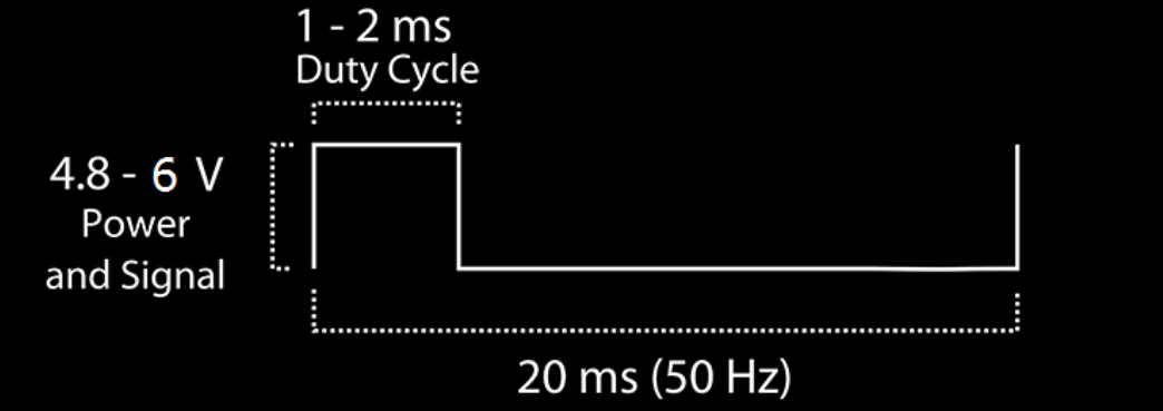
Control Signal
The angle of the servo is controlled by the Positive Pulse Width of a 50Hz square wave.
- A pulse width of 2 ms correpsonds to +45 degrees
- A pulse width of 1.5 ms correpsonds to center
- A pulse width of 1 ms correpsonds to -45 degrees
Code Pt. 1
Use the following pseudo-code algorithm to write a proof-of-concept servo demonstration.
Note that 20ms is 50Hz: 20ms * 50 = 1 second.
Loop Forever { Repeat x50 { 1ms V-high pulse 19ms V-low} Repeat x50 { 1.5ms V-high pulse 18.5ms V-low} Repeat x50 { 2ms V-high pulse 18ms V-low} } CPU Timed Pulses - as a Function
#define SERVO_SIGNAL_PERIOD_US 20000

...

void servo_set_level(float level, int duration_ms){
		// first calculate the pulse for the level.
		// -1.0 = 500 us    0 = 1500 us      +1.0 = 2500 us
		int pulse_w = (1000 * level) + 1500;
		// next calculate the number of pulses. Remember 1 pulse = 20ms
		///    e.g. 1000 ms -> 50 pulses
		int n_pulses = duration_ms / (SERVO_SIGNAL_PERIOD_US/1000);
		// do a 'for loop' for that many pulses
		for(int i = 0; i < n_pulses; i++){
			gpio_put(SERVO_GP, 1);
			sleep_us(pulse_w);
			gpio_put(SERVO_GP, 0);
			sleep_us(SERVO_SIGNAL_PERIOD_US - pulse_w);
		}
}
PWM Frequency and Duty Cycle
For part 3 you will attempt to set up the PWM module to generate a 50Hz control signal.
- Each PWM signal frequency is controlled by Clock Divider and Wrap values for the cpu clock slice.


- The CPU Frequency is 125 MHz by default.
- The Clock Divider is an unsigned 8-bit value and can be 1 to 255.
- The Wrap counter is an unsigned 16-bit value and can be 1 to 65535.

- The Level counter controls the pulse width or duty cycle.is an unsigned 16-bit value and can be 1 to Wrap
- The value of the Level counter can be 1 to (Wrap). It is also an unsigned 16-bit value.