Microcontroller Unit Lab 4
RC Servo Control Signals
Summary
Use a microcontoller to provide a pulse width control signal for an RC servo.
Pt. 1 Create a simple repeated movement sequence using CPU-timed pulses
Pt. 2 Add two buttons. Each should move the servo by a fixed angle increment. One for clockwise and one for counterclockwise rotations.
Pt. 3 Replace the CPU timing with Pulse Width Modulation control where the PWM freqency controls the motor speed.
Required Equipment and Supplies
- MG90S Servo Motor datasheet
- Rasperry Pi Pico with Headers - pinout diagram
- Momentary Switch (Push Button) [x2]
- 15kΩ Resistor [x2]
- USB Micro Cable
- Breadboard
- Cables and 22ga wire as needed
Wiring
- Because the MG90S servo has small power requirements, you may power everything from the USB cable.
- Use VBus or Vsys to supply your breadboard power rail from the Pi Pico.
- The MG90S has only three wires to connect. V+, Ground and Signal.

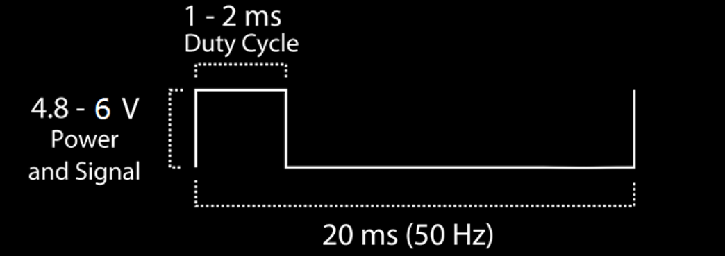
Control Signal
The angle of the servo is controlled by the Positive Pulse Width of a 50Hz square wave.
- A pulse width of 2 ms correpsonds to +45 degrees
- A pulse width of 1.5 ms correpsonds to center
- A pulse width of 1 ms correpsonds to -45 degrees